
Thursday, September 18, 2014

Manjaniq (Early) # 2
 |
| Rear View showing the sack of rocks that is the weapon's counterwieght. Note the crossbow fastened to the rear of the weapon, used for the return of the weapon to "firing" battery. |

Tuesday, September 16, 2014

Pyrotechnic Weapon; Greek Fire Syphon
 |
| The hypothetical reconstruction is based upon written descriptions and one surviving illustration. A vertical brass pump provides air pressure via a bronze-bound leather hose to the main tank consisting of two pieces of copper sheeting soldered together. Underneath is a small brazier and a pair of bellows. Another hose takes the heated liquid to the nozzle. Redrawn and Enhanced by Marcus Audens. Reference: D. Nicolle, "Medieval Soege Weapons (2)," Osprey, 2003, New Vanguard 69. |
Torsion-Powered Engine - Byzantine "alakation or ballista"
 |
| This weapon is probably a simplified version of a weapon common during the Roman period. The weapon could be aimed up and down and side to side. It had two separate bow arms (oak) and twisted skiens stretched across a wooden frame. A crosspiece of iron with a claw is held in place by two staples nailed to the stock. An iron "key" with a length of rope served as a release mechanism. Redrawn ad Enhanced - Marcus Audens Reference: D. Nicolle, "Medieval Siege Weapons (2)," Osprey, 2003, N.V. 69 |
Torsion-Powered Engine; "Qaws ziyar" by al Tarsusi
 |
| The frame of this equipment is unseasoned oak, put together with half-butt joints, and large iron nails. Each piece of wood used in the construction of this weapon was approximately one span (20 cm) square while the vertical timber at the front of the weapon was two spans across with bronze plates around both sides of an arch shaped hole through which the arrow / dart was shot. Twisted skiens of horsehair and silk were looped around the frame. In the above drawing the bowstring has been pulled back into a slot cut into a groove across the top of the horizontal stock. The oak trigger pushed up a pin releasing the bowstring. Redrawn and Enhanced by Marcus Audens. Reference; D. Nicolle, "Medieval Siege Weapons (2)." Osprey, 2003, N.V. 69 |
Thursday, September 11, 2014

Shabakah -3, Back Side
 |
| The rear panels of heavy cloth and raw wool has been removed to provide a view of the rope net under the over- layers |

Shabakah 1
 |
| The above is a screen which was used to protect siege workers from darts and arrows launched from special catapult siege machines. It was designed to stop and hold such missiles. |


Sunday, August 31, 2014
Pyrotechnic Weapons -- Naft Zarraga
 |
| The above conjectural drawing is a reconstruction of a portable Greek Fire siphon from a number of written descriptions plus highly stylized illustrations in Byzantine and Islamic military manuals. An airtight copper "box" (tank) containing inflammable liquid is mounted above a hand-held siphon. Reference: D. Nicolle, et al, "Medieval Siege Weapons (2)," New Vanguard 69, Osprey, Oxford, UK, 2003 |
Pyrotecnic Weapons, Hand-gun late 14th century
 |
| Unfortunately, the very worn Arabic inscription on the rear of the portion of the Islamic Gun (1) has yet to be interpreted. The massive late medieval iron arrow (2) found in the citadel of Damascus and now in the Musee del' Armee in Paris was probably fired from such a gun. Reference: D. Nicolle et al, "Medieval Siege Weapons (2)," New Vanguard 69, Osprey, page 45 |
Monday, August 11, 2014

Tuesday, August 5, 2014


Thursday, July 31, 2014


Sunday, July 27, 2014

Monday, July 14, 2014

Friday, July 11, 2014

Tuesday, July 8, 2014


Three styles of "Manjaniq," or catapult
 |
| (1) Turkish Style "manjaniq"; (2) Rumi, Frankish Style "manjaniq"; (3) Top wooden support; (4) Byzantine Petrbole |
Tuesday, July 1, 2014


Monday, June 30, 2014

Friday, June 27, 2014

Sunday, June 22, 2014
Baghdad; Round City and section through gate - Abbasid, Iraq
 |
Baghdad, of course remains the most famous memorial to the Abbasids,
although nothing remains of the fortified Round City built for the Caliph
Mansur (754 - 775). Its purpose was to serve as an administrative capital,
a Caliphal palace, and a place to settle thousands of Khurasani-Arab troops.
The location of Baghdad was also particularly good for communications.
Militarily it housed a large army at the center of the state; these forces
included regular troops, the Caliph's own guard, the city's shurta police
and haras internal security force, as well as Baghdad's own paramilitary
militia. The great majority of the population, which may have reached
as many as a half-million by the year 800, lived in sprawlingsuburbs
around the Round City, some of which had been built by Khurasani
military chiefs to house their own followers.
D. Niccole and Angus McBride(illus.), "Armies of the Muslim Conquest," Men-At-Arms 225, Osprey Pub., 1993, Pages 23-24. Respectfully Submitted; Marcus Audens |
Friday, June 20, 2014


Qala'at Rustaq, Early Islamic Oman
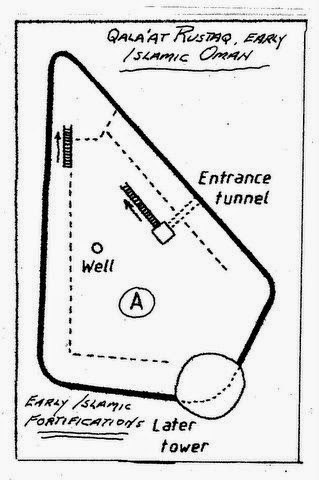 |
The 'later tower' means that sometime since the fortification was
constructed, a tower was added to the curtain wall. It was
well known that as european forces came into contact with
muslim forces at a fortification, the Muslim engineers, borrowed
the technology that they saw in the improvements of their
opponent's fortifications .
|
Muslim State at the Death of Muhammad in 632 CE
 |
| Reference: D. Nicolle, et al, "Armies of the Muslim Conquest," Men-At-Arms 225, Osprey, 1993, P. 4 |
Monday, April 7, 2014
"Ship's Prow Tortoise" #7
 |
| This view of the machine shows it right side up. Note the two iron plates for shunting aside any flamable material or logs used against the machine In the top vee of the angle one can see the hinge assembly for the main brace timber. |
"Ship's Prow Tortoise" #6
 |
| This view of the tortoise shows the machine upside down, showing the wheels, axles and crossbrace. |
"Ship's Prow Tortoise" #5
 |
| The hieght of the two wings from the ground was about seven feet, which was enough to protect the workers behind the tortoise wings. |


"Ship's Prow Tortoise" #2
 |
| This picture shows the Tortoise lying on it's side showing the four wheels, two axles, and the brace timber. |
"Ship's Prow Tortoise" #1
 |
| This is a picture of the Tortoise upside down showing the four wheels which enabled the workers in the field to move the tortoise around. This siege machine was used to protect workers, on a slope, from materials that might have been rolled down the slope such as barrels, logs, etc. The Tortoise had two iron plates on the sharp end of the prow to shunt aside any burning materials such a a wagon load of hay, a flaming barel of oil, etc. The sharp end of the Tortoise (prow) was always pointed up-slope and the large timber in the middle was the brace that held the tortoise in place. The center brace and both ends of the tortoise were held in place by heavy stakes pounded deep into the grond. |
Friday, March 21, 2014

Subscribe to:
Posts (Atom)
